Showing posts with label Audio. Show all posts

Tuesday, July 30, 2024

Excessive Single Side Band Transmission, also know as ESSB or eSSB.

There seems to be an increase in the transmit bandwidth range for SSB communications, which traditionally operates within a narrow-band of approximately 3 kHz. Now if we go with a 3 khz “Voice channel” for Single Side Band (SSB) then the Transmitted Bandwidth, let's call it the TxBW, should fit into the range 0-3000 kHz.

However, I’ve noticed more and more operators use a TxBW of 4 kHz or more. This is often referred to as Extended Single Side Band (ESSB) which I have seen to extend in some instances even to 5 kHz and more. The claim to fame is HiFi Audio.

Now Amateur Radio is an experimental hobby, so this, on the surface, shouldn’t irk anyone, shouldn’t it? However, I frequently encounter ESSB operators on 20 and 40m talking to operators who have not modified their station for ESSB communications, i.e. a station with a TxBW 5 kHz to a station with a 3 kHz Receiver Bandwidth, lets call that RxBW.

So what seems to be the issue?

Let's say a QSO is conducted on 14.229 MHz, one operator uses a TxBW of 2.9 khz and the other uses a TxBW of 2.4 kHz. Signal are good with about S7 both ways. Since this is conducted using the Upper Side Band and, if we apply a Voice Channel spectrum of 3 kHz the used frequency spectrum for that QSO is from 14.229 – 14.231 MHz (not quite but let's stick with 3 kHz). Stations operating on 14.232 MHz should not have any issues operating. However, let's assume one of the operators is operating at a TxBW of 5 kHz. This situation would infringe stations operating on 14.232 MHz quite badly. Another example would be if a DX station is calling on 14.232 MHz and I would like to work that station. However, I will be unable to do so due to the excessive TxBW of the ESSB operator (14.229 - 14.234 MHz)

Anyone see an issue here? Well, I do! However, the question is does the ESSB operator see the issue? From my experience most ESSB operators do not.

So why use 5 kHz TxBW whilst conducting DX contacts. Aren't we trying to share the limited frequency spectrum between all Amateurs? There is certainly NO benefit to the station receiving the ESSB station. 

Frequency spectrum during “openings” are crowded and transmitting with a 5 kHz TxBW during these opening does not show any courteousey towards other spectrum users.

The above shows an Australian Operators transmission with a TxBW of  5 kHz and the DX station using a  less than 3 kHz “Voice Channel”. I will assume that the DX stations RxBW would not be more than it's TxBW.

NOTE: I’m referring to the TxBW and not the Intermodulation Products (IM) or “splatter”, e.g. the light blue “hair or whiskers” on either side of the signal, which are obvious related but are not discussed here.

This is even more frustrating on the 40m Band, as there are more an more local stations operating with a TxBW of greater than 4 kHz. 

Now Amateur Radio is an experimental hobby and experimenting with a TxBW > 3 kHz does fall under this category. So, yes I believe in experimenting but this is not experimenting, this is not understanding the implication of excessive TxBW. And believe me I’m all for experimenting. However, I am quite happy with a 2.4 kHz well balanced audio TxBW which would influence the use of an appropriate RxBW.

Additionally I believe that these operator would not know how much "real" power they are transmitting. If we talk about 400W PEP, then the average output power would be rather LOW.

NOTE: I also observed that these type of operators seem to drop their TxBW to 3 kHz during Contests!?!  Yet they seem to believe that during crowded DX sessions it is OK to use 5 kHz or more TxBW. Isn't that a bit hypocritical?

Since Amateur Radio is a self regulating hobby it might be about time to add a frequency spectrum for those inclined to use ESSB. I believe this has been done for certain other modulation schemes (AM/FM/DIGITAL).

Tuesday, April 2, 2024

Current TX Setup

Currently I do not use the dbx in the audio chain. I use an old HEIL PROSET PLUS (HPP) headset which I purchased second hand. Now the headset itself is just average, normally I'd be using a Sennheiser for its nice fit, excellent sound reproduction and lightweight. However, the HPP headset does have the original HC4 and HC5 microphone inserts and because the dbx in in service for a different radio I opted for the HPP for the time being.

The current setup is:

    • HHP (HC5)
    • TX Bass: +3
    • TX Treble: +4
    • TBW: 200-2500
    • COMP: 8
    • MIC GAIN: 35%


Wednesday, November 16, 2022

Why I chose to use an Audio Processor

I have been asked several times why I have chosen an external microphone processor. So, I thought it was time to put my reasons down on paper.

Some new amateur radio transceivers come with a reasonably good microphone and sound quite good when set up correctly. However, I'm not a hand-mic type of guy, and I'm also not a desktop kind of guy. When using a desktop mic, I either end up needing to go to the physio more often to get the knots out of my neck or it ends up becoming a "hand-mic".

Throughout my pursuit for a well-balanced SSB transmit audio, I have learned a little bit about audio bandwidth and how to squeeze my dulcet tones into less than a 3.3kHz audio bandwidth.

But I digress. To answer the question, I went with a dynamic studio microphone, and for that, I needed outbound amplification to drive the microphone. I also wanted/needed a bit of equalizing and compression to the audio signal. Additionally, I wanted to restrict some of the background noise that we all seem to endure at odd occasions. Therefore, my requirements became the following:

  1. It needed amplification.
  2. I also wanted rudimentary filtering (EQ).
  3. It needed noise gating.
  4. It required compression that is smooth.
  5. It should fit my hobby purse.

With my wishlist sorted, I looked at what was available at a reasonable price. There are a lot of processors available, but most of them break my hobby purse. However, I finally found that the dbx286s ticked all my requirements, including requirement #5, the cost.

Here is a quick rundown of how the dbx286s fulfills my requirements:

1. Amplification: The pre-amplifier gain control runs from 0dB to 60dB, has 48V PHANTOM POWER if a condenser microphone is being used, and an 80Hz High Pass Filter (rumble filter) to take care of any rumbling at low frequencies. This is a very steep 18dB/octave high-pass filter. This filter will also, to some extent, reduce the proximity effect one gets with directional microphones.
 
2. Filtering: The dbx286s has a two-stage enhancer, the LF DETAIL and the HF DETAIL. Most enhancers work by adding a controlled amount of distortion to the audio signal. However, the dbx286s functions like an equalizer. One interesting aspect is that the LF DETAIL control applies a boost at 80Hz and a cut at 250Hz simultaneously. Many of us are aware that boosting low frequencies will often make the sound quite muddy. However, this "muddiness" is usually due to boosting frequencies other than those that would subjectively add bottom end to the signal.

You might be wondering why the 80Hz boost frequency is the same as the frequency to cut in the mic preamp stage. Well, the preamp comes before the compressor, and by removing the 80Hz before the compressor, we eliminate the compressor acting on the low (rumble) of the audio signal. This is quite different from the way AR transceivers are using MIC-GAIN and COMPRESSION.

3.Expander/Gate: Gating the audio signal to reduce background noise is a bit of an art form, and it took me quite a while to get it right. On the 286, there are two adjustments we can apply: THRESHOLD and RATIO. The ratio is adjustable up to a level of 10:1, and the threshold is variable from OFF to +15dBu. This allows me to reduce low-level clutter in the audio signal, such as breaths, without affecting the vocal itself. It's important to remember that compression raises the noise floor of the audio signal. The expander has two LEDs, one red (-) and one green (+), indicating when the audio signal is below or above the threshold. However, I found setting the gate was easier by listening to my transmitted signal on a second receiver.

4.Compressor: The compressor has two adjustments: DRIVE and DENSITY. The compression is of the over-easy type, which means the ratio increases as the audio level gets higher. This means that the Drive control controls the degree of compression. With just these two controls, I can get a very smooth compression and apply it carefully to avoid sounding over-compressed. Additionally, the 8-stage LED bar-graph shows the amount of gain reduction occurring during compression. This is quite different from the compression used in AR transceivers.

5.Cost: Yes, I achieved this requirement. The microphone and microphone processor, at the time of purchase, set me back slightly over $0.6K.
 

Saturday, June 11, 2022

Listen to the Music

Listen to the music, but not on SSB with a 3kHz bandwidth. What I mean is, listen to the Amateur Radio Bands, and you will quickly understand what I'm talking about. Some of the audio signals on our bands are appalling. Even worse are some of the reports that people are relaying back to these poor operators.

It's worth noting that many amateur radio operators strive to have a clean and pleasant signal. However, both the amateur radio community and society, in general, have become non-constructive regarding any form of insights or criticism. Therefore, the information below may help some operators check their transmission quality.

A little bit of research on the internet reveals that the human voice contains frequencies ranging from about 100Hz to 8000Hz. However, only the energy between about 300Hz and 3800Hz contributes to the intelligibility of speech. Vocal content below 400Hz provides "body" to the voice, which is great for singers and radio announcers. Speech content above 3000Hz provides presence and can aid communication, to some extent. However, the added bandwidth can introduce noise and other complications.

In my opinion, in a Single Side Band (SSB) communication system, it's crucial to achieve the highest Signal-to-Noise Ratio (SNR) at the receiving station under strenuous propagation conditions to get the message across. To achieve this goal, we should transmit the portion of the human speech that affects articulation the most, which research has shown to be the spectrum between 300Hz and 3300Hz.

These bandwidth limits have been established in the days of long distance telephone systems and have served the telecom industry of our world quite well.

The standard SSB TX filter in most SSB transceivers is 2.7kHz wide, and a well-adjusted SSB transceiver has this filter aligned so that it will pass audio between 300Hz and 3000Hz. Since SSB transmitters are peak power-limited, transmitted energy below approximately 250 Hz will show power on the power meter but will not contribute to the articulation at the receiving station. However, these days we often see signals with a "power-grab" dominating the bands. Many operators focus solely on increasing their power output, resulting in signals that are difficult to copy and interfering with other spectrum users on either side of the selected channel. These bass-heavy signals can swamp the AGC in a receiver, creating a low-frequency rumble that is unintelligible and potentially causing issues for other spectrum users.

Fortunately, with the availability of publicly accessible Web-SDR systems, it's now possible to monitor one's own transmissions quite easily. 
The way I do this is however, slightly different as described below. 

To set up a transmission check, I first record a test transmission and play it back through the transceiver which is connected to a dummy load/antenna. While transmitting the recording, I listen to the signal using a second receiver (in my case, an SDR-IQ) to adjust the TX-audio profile, including the TX Bass and TX Treble on the ICOM, MIC gain, and compression.

When adjusting compression, I make sure to adjust the MIC gain so as to avoid the compressor pumping up background noise during speech breaks. By listening to my own transmission, I can tailor the audio characteristics to ensure that all transmitted power remains inside the available SSB channel. This is particularly important for QRP stations or foundation license holders, as losing just 3dB to either side of the channel means that only a quarter of the peak power is transmitted inside the wanted SSB channel, potentially making it difficult for the receiving station to copy the signal.

Below is a display of a test I conducted to get a more balanced audio profile. The LSB signal within the top of the waterfall in the below picture is showing emphasis on the low end of the audio spectrum. Visible on the bright red right hand area. Below this signal we can clearly see that I have selected/created a more balanced audio profile.


Analysing those signals, we can see that the first signal has quite a lot of emphasis on the lows, at around 100-400Hz (on the right the big red line). This makes the signal sound rather bassy, and although it shows a lot of power on the power meter, it is not overdriven (like most of the signals on the bands today)
Operators who prefer to use wide-open audio filter might find this sounds okay. But for longer distances, were the receiving station only has a bit better than marginal reception, say S5, it would be difficult to copy.
The second signal shows much better-balanced audio and I would classify this as very good communication audio. However, the bandwidth of both signals is approximately 2.9kHz (100-3000Hz) which is still in the 3kHz channel bandwidth. I believe that the bottom signal would still sound rather nice at a 2.6, 2.4kHz bandwidth even in 2.1kHz with a lot less noise bandwidth this signal would still sound Q5.

Oh and ESSB enthusiast find my view of the use of narrow band audio for SSB harrowing. However, it would be nice if these OM's would find a space in our limited spectrum were they would NOT interfere with low power stations that they might not hear.
I've been seeing quite a few ESSB operators on 40m clobbering small signals due to their inability to hear those stations and make it difficult for others to make the contact with those stations. 
Also, I don't believe that ESSB should be used during a contest where bandwidth is limited, not even by a contest station.

Thursday, January 20, 2022

A quick description of the Audio configuration I use with my ICOM IC-7610.

Updated 2022-10-15:
Updated 2023-04-21:

Here is a quick diagram of how everything is connected.

Corrected 2022-10-15

The Microphone is a condenser mic, an AKG CK47 with a HM1000 mount HEIL GM with the HC5 selected, which goes into a dbx286s. From there it goes through an isolation transformer and then into the ACC1 port of the ICOM. There is no Mic connected at the front and as such PTT is also through ACC1.

NOTE: 
If you want to use the VOX you're out of luck, it looks like that by going through the ACC port the audio is by-passing the analog audio circuitry, hence VOX won't work with this setup.

I did get asked as to "WHY" I've been doing it this way?
Well, my reasons are:
  1. The attenuator is there to be able to limit the Audio Voltage ingress into the radio (i.e. as to not to overdrive the transceivers audio input stage). It is a bit of an insurance to not have the input stage of the transceiver to flat line. 
  2. Using an isolation transformer is to isolate the external Audio circuitry (dBx) from the transceiver to avoid ground loops and associated issues (HUM).

The dbx286s is setup as followed:
      1. Mic Preamp
        • +45dB +50dB
        • Phantom Power
        • 80Hz high-pass
      2. Compressor
        • Drive 7 5
        • Density 5.5 5
      3. De-Esser
        • Frequency 4k
        • Threshold 2
      4. Enhancer
        • LF Detail 2.5 7.5
        • HF Detail 10
      5. Expander/Gate
        • Threshold -28 -15
        • Ratio 5.1:1 2:1
      6. Output
        • -0 dB
Please note this configuration suits me, i.e. it is for my voice profile, it might not suit your voice and should only be seen as a setup guide.

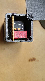
Here is a picture of the isolation transformer with attenuator. The input is from the dbx and the output goes to the ACC1 port, Pins 4 and 2. The transformer I used is an old line isolator for Telephone modems, an ETAL-P1200. I have a few more isolators from old Telecom exchanges but, they are a bit bigger and didn't fit into the case I've had laying around. Also, I took the easy way out in cabling the isolator (not enough space in the case), the doco for the P1200 does show us how to use it properly.


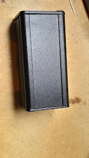
And a blurry photo of my quick build


To connect to the ICOM, I wired a DIN 8 pin to connect to the ACC1 port as followed:
  • Pin 4 (Audio input) and Pin 2 (GND),
  • Pin 3 (PTT) and Pin 2 (GND) using a handfootswitch.

Here is an extract from the ICOM manual.


And here is the new audio profile for the IC-7610 with the AKG HEIL GM5 mic.

Transceiver Setup:
    1. TX SSB Setup
      • TBW (NAR) 200-2500 (TX-BW 2K3) prefered
      • TBW (MID) 100-2700 (TX-BW 2K6)
      • TBW (WIDE) 100-2900 (TX-BW 2K8)
      • TX Treble +5 -2
      • TX Bass -3 0
    2. MOD INPUT
      • ACC MOD LEVEL 20% 15%
      • DATA OFF MOD MIC, ACC <-- MIC needed for VOICE TX
    3. COMP
      • Level 3 6
      • TBW Depends on the mood. (see TX SSB Setup)
Below are a few pics of a second unit I've build. Which, according to the ETAL documentation has better audio transfer characteristics.


The new interface is now connected to the ICOM IC-7610 and the old interface to the ICOM IC-9700. By splitting the output of the dbx, I'm able to use a single Mike for either radio. However, each Radio has its own PTT though.