Saturday, January 29, 2022

What is your S-Meter actually displaying!

To check the S-Meter on a HF transceiver against the IARU 6 dB standard, you will need to follow a few steps:
  1. Connect a known RF signal source, such as an RF signal generator, to the transceivers' antenna input.
  2. Set the RF signal generator to output a signal at a frequency and power level that is appropriate for the transceivers' band and mode of operation.
  3. Use an attenuator to reduce the RF signal level in 6 dB steps. You can use a set of switchable attenuators, a variable attenuator or individual attenuators to achieve this.
  4. Connect a device that can read either power or voltage, such as a digital voltmeter (DVM), digital multimeter (DMM), power meter (PM), or cathode-ray oscilloscope (CRO), to the output of the attenuator.
  5. Adjust the attenuator to reduce the RF signal level in 6 dB steps and record the corresponding S-Meter readings on the transceiver.
  6. Compare the S-Meter readings to the IARU 6 dB per S-Unit/point standard to determine if the S-Meter is tracking correctly.
  7. If necessary, adjust the S-Meter calibration on the transceiver to match the IARU standard.
It's important to note that the accuracy of the check will depend on the accuracy of the RF signal generator, attenuator and the measuring device. Which mean that to get the most accurate results it would be advisable if ones equipment had been checked against calibrated equipment.
In the past, I have used an Elecraft XG3, which I checked against a NIST calibrated LP-100A. Which in turn helped to characterise a set of switchable attenuators.
Below, you will see some photos depicting an array of attenuators and the XG3 with a step attenuator in action.


The picture on the left is showing the test setup using the Elecraft XG3 and a switchable attenuator to check S-meter tracking on my radio. As long as the test equipment has been checked against a know standard we can make fairly accurate checks using basic test equipment.


And here to the right, an assortment of attenuators.


Below is a pictorial/sketch of the current test setup I use to check the accuracy of a Radios S-meter.


Staring on the left is the signal-generator, followed by two attenuators, one in steps of 1dB and the next in steps of 10dB. The next device is a 6dB splitter which splits the signal from the signal-generator in two reduced signals. One signal going to a calibrated power-meter and the second signal to the test subject i.e. our receiver. We could replace the power-meter with a Voltmeter.

However, if the signal-generator has an accurate signal output display this can be simplified by removing the splitter and the power-meter. Using this test setup it is very easy to make sure that the check of the S-Meter is accurate. As the above picture shows, to compensate for the losses of the test setup, the signal generator is set to provide a -66 dBm signal. This is about 7 dB higher than the -73 dBm level to compensate for the additional losses, 0.7 dB from the interconnections and attenuators, and about 6.3 dB from the splitter.

Equipment used:

NOTE: Whatever signal source or attenuator you use, make sure that its accuracy has been checked against a known reference.

The equipment I've used has been checked and aligned where necessary against NIST-certified instruments including an LP-100A RF power-meter, a Boonton RF power-meter with a 51011-4B sensor, a Fluke 8842A DMM, and a Brymen BM-869s DMM.

Thursday, January 27, 2022

S-Points, are they useful

The S-Meter in an Amateur Radio Receiver/Transceiver is an indicator for the received signal strength (Strength Meter). On HF, signal strength 9 (S9) has been defined to be an input power of -73dBm @ 50Ω (dBm is power expressed as decibels relative to 1mW). This is a level of 50µV (microvolts) measured at the antenna input port. Each step between S-Units corresponds to a difference of 6dB. 6dB is equivalent to a power ratio of four and a voltage ratio of two. (S-Point History)

The term S-Unit/point is used to refer to the amount of signal strength that move the S-Meter indicator from one marking to the next, i.e. it moves by one S-Point/unit. On Amateur Radio equipment, most S-Meter markings are from S1 to S9, with marking above S9 in 10dB steps.
To be able to add meaning to the S-Meter report, I believe, Amateur Radio Operators should know how the S-Meter of the radio equipment is tracking against the IARU standard. Quite a few Amateur Radio Operators either don't seem to care or don't understand the value of having an instrument that can track precise. Let's consider the below.
  • Profiling a couple of antennas by listening to the background noise.  On antenna one we see a noise level of S4 (-103dBm). Switching to the second antenna we see that the S-Meter indicates S6 (-91dBm). We could now conclude that there is a noise difference between ant1 and ant2 of 12dB.
  • Checking the front to back ratio of a Beam (Yagi/Uda) Antenna. Receiving the signal from the front of the antenna the meter reads S9. Turning the antenna 180 degree, i.e. pointing the back of the beam to the signal source, the meter reads S5. This would indicate a nice 24dB(4 S-point = 4*6dB = 24dB) front to back ratio of the Antenna.
  • Comparing receiver prowess, i.e. using a receive splitter to split the receive signal equally to compare receivers. If receiver-1 is displaying a S3 and receiver-2 is displaying S7 on the same signal. 
We can clearly see that if we do not know what our S-Meter really is displaying, every above scenario becomes guess work and would most likely lead us astray.
 
So to come back to the question at hand, I'd say since Amateur Radio is a Technical Hobby it would be nice to provide and receive a correct S-Value report, one that is trackable to a standard. An even better report would be SNR (one for the future).
However, if one uses the Radio for NET chats and contesting, then who cares if the S-value is S9 or S9+20dB or S5 for that matter.
Would it then not be more appropriate to say the quality of your signal at my station is Q5 or Q4, i.e. going back to the old Q(SA) system. One can always ask for an S-value, but what would be the usefulness in a value that does not track to a standard.

Wednesday, January 26, 2022

A little history about S-Points

The evaluation of signal strength using S units in the RST system was developed in 1934 by the Radio Amateur W. Braaten, W2BSR, and adopted in 1938 by the ITU. As receivers in the past often lacked a reception level indicator (S-meter), the RST system was based on a subjective hearing assessment of the received signals. S1 represented a barely audible signal, while S9 represented a very strong signal. In 1981, the International Amateur Radio Union (IARU) assigned shortwave reception up to 30 MHz the following S-levels, starting with the upper reference value of 50 microvolts (-73dBm) for an S9 level. Each S-level below is half the voltage of the previous level, with a level of 0.2 microvolts (-121dBm) assigned to an S1 level. Since a voltage ratio of 1/2 (50% or 0.5) corresponds to a 6dB decrease on a logarithmic scale, the proverbial "6dB per S value" was established.

NOTE: One S-Point really equates to 6dB!

Received VoltageReceived Power (Zin = 50 Ω)Signal Strength (S-Value)
-14.0 dBμV0.2 μV-121 dBm1
-8.0 dBμV0.4 μV-115 dBm2
-2.0 dBμV0.8 μV-109 dBm3
4.0 dBμV1.6 μV-103 dBm4
10.0 dBμV3.2 μV-97 dBm5
16.0 dBμV6.3 μV-91 dBm6
22.0 dBμV12.6 μV-85 dBm7
28.0 dBμV25.1 μV-79 dBm8
34.0 dBμV50.1 μV-73 dBm9
40.0 dBμV99.9 μV-67 dBm9 +6
44.0 dBμV158.3 μV-63 dBm9 +10
46.0 dBμV199.3 μV-61 dBm9 +12
52.0 dBμV397.6 μV-55 dBm9 +18
54.0 dBμV500.6 μV-53 dBm9 +20
58.0 dBμV793.4 μV-49 dBm9 +24
64.0 dBμV1.6 mV-43 dBm9 +30
74.0 dBμV5.0 mV-33 dBm9 +40
84.0 dBμV15.8 mV-23 dBm9 +50
94.0 dBμV50.1 mV-13 dBm9 +60

As such the S-Meter/indicator should display the receiver input voltage divided into S levels from S1 to S9 based on 6dB per step.

Oh no, there is no S0

Yes, to the surprise of some people, there is no S0. There is no S0 because it represents the absence of a signal, which is not measurable.

An observed on-air signal report: "I have noise on the frequency, so your signal report is R5 by S0 to S1" this can be confusing, as S0 really means I can't hear anything.

On the other end of the scale, input voltages greater than S9 are displayed as "x dB over S9". I have found that most newer HF-Radios are tracking fairly good above S9 and that S9 also seems to be fairly accurate to the -73dBm/50μV.

The definition of S9 = 50μV (-73dBm) as the reference level for frequencies up to 30 MHz was based on the sensitivity of conventional receivers at the time and the atmospheric background noise typically present at shortwave (a different reference level applies above 30 MHz).

Most S-meters are not exact level indicators but simply display the AGC control voltage. The result is often no more than an estimate of the actual input voltage. However, accurate S-Meters (low-power level meters like a field-strength-meter) are quite possible by tapping the IF and using log-amps as can be seen here (page 21), and of course in software as in Software-Defined Radio (SDR).

Remember that S levels are not a physical quantity, they are but a practical tool for the simple specification of received field strength levels. A better choice would be a meter with a scale in dBm or μV, but only if the meter tracks properly.

NOTE: Due to the lower external noise above 30 MHz, a higher receiver sensitivity is required at VHF.

For this reason, the reference level for S9 was set ten (10) times lower for the frequency range above 30 MHz at an input voltage of 5μV. However, the 6dB step remains the same.

Checking my transmitted radio frequency spectrum

Using an ICOM IC-7610 into an amplifier which is connected to an 800W homebuilt dry dummy-load for testing. Now I could drag one of the Spectrum Analysers up to the shack or bring all the AR-equipment downstairs (fat chance). So I decided to use my trusty old SDR-IQ. As this is not an accuracy test/measurement rather a quick check to see how the signal looks before it goes out into the ether. Using an SDR and a PC makes it easier to snap pictures of the result for later comparison.

Here is a quick view of the setup:


TRX : IC-7610
AMP : SPE
LOAD: 50Ω 800W with 40dB Tap
ATT : 20dB
RX  : SDR-IQ
PC  : Laptop with Spectraview 3.39 connected to RX via USB2

The below picture shows me what my transmitted signal looks like. Instead of using my Elecraft two-tone generator I was using my voice and by creating a rather harmonic rich sound (don't ask, the wife came running in and thought I needed attention) the below spectrum showed up on the "Spectrum Analyser".


And here is my Voice caller, calling CQ ....


And here is a spectrum display using a TX bandwidth of 2800 Hz, 100-2900.


Even running a wide audio setup the spectrum of the signal is well contained.

Here you can see how my ICOM IC-7300 fared when checking the output signal.

Here is a device you could use to monitor your transmission with a cheap SDR receiver, a CRO or a Spectrum Analyser.

And below is a spectrum plot of my signal on 20m:


Saturday, January 22, 2022

Do the old analog radios have better receivers than the new breed of SD-Radios?

I've had an interesting conversation this morning on 10m SSB. The conversation started about my audio being a bit "sharp" which, I guess, it might be at a 2.3kHz transmit bandwidth (200-2500) from my ICOM IC-7610. I've been explaining that I like to use less bandwidth to share our frequency spectrum more equally and avoid splattering across the spectrum. At which stage my QSO partner mentioned that he found me because I was splattering across the band whilst he was using his Kenwood TS-440. 

During the conversion he mentioned that he also had an IC-7610 and that he would like to get an audio report from me. So the TRX got switched and we progressed the QSO. To his amazement he found that I did not splatter on the ICOM. Yet he was adamant that the Kenwood would/should be the better receiver.

I was quite confused about this. Why would he think that? What would be the reason to buy one of the most modern radios, but believing that the old, and let's face it the TS-440 only have a good reputation amongst the CB fraternity, would outperform one of the more modern radios on this planet. 

Now, I have used quite a few Amateur radios in the past, the likes of an Elecraft K3 with added 2.8, 2.1 and 1.8kHz roofing filters, an ICOM IC-765 with Inrad roofing filter mod, Yaesu FT-5000MP with 2.7kHz roofing filter, even some of the newer, direct sampling SDRs like the ICOM IC-7300 and the ANAN 100D. Additionally I've owned and operated a DRAKE TR7, a Kenwood TS-520, a couple of YAESUs, the FT-101, FT-901/2, FT-757GX, FT-2000, FT-5000dx and an FT-817, also some ICOMs the likes of an IC-706, IC-730, IC-735, IC-7000, IC-7400. They all got purchased according to a few criteria but the main criteria was $$$ and then RX performance. These days a few more aspects have come to dictate the purchase of a new toy, but that is for another story.

Please note, that I'm not talking about LAB tests, even though I have done and still do receiver and transmitter test to get to know what the radio is capable of in my environment. I'm talking about the day to day use of these radios at an average QTH with average antenna systems. Most of these radios are far better than a Kenwood TS-440, which I might add I had the privilege of using during a contest and a field-days (what a debacle that was), only the FT-757GX I'd say was worst in the TX and RX department than the TS-440 and maybe the IC-706 in the TX department but this was bought purley as a mobile rig. 

Anyway, based on my experience, I have to say that my answer to the question would be a resounding "definitely not in this case".

73 

UPDATE 12/2023: The operator is now using his IC-7610 and it is the best thing since sliced bread. Oh and he change his callsign from VKx1234 to VKx123 and no, no Licence upgrade.

Thursday, January 20, 2022

A quick description of the Audio configuration I use with my ICOM IC-7610.

Updated 2022-10-15:
Updated 2023-04-21:

Here is a quick diagram of how everything is connected.

Corrected 2022-10-15

The Microphone is a condenser mic, an AKG CK47 with a HM1000 mount HEIL GM with the HC5 selected, which goes into a dbx286s. From there it goes through an isolation transformer and then into the ACC1 port of the ICOM. There is no Mic connected at the front and as such PTT is also through ACC1.

NOTE: 
If you want to use the VOX you're out of luck, it looks like that by going through the ACC port the audio is by-passing the analog audio circuitry, hence VOX won't work with this setup.

I did get asked as to "WHY" I've been doing it this way?
Well, my reasons are:
  1. The attenuator is there to be able to limit the Audio Voltage ingress into the radio (i.e. as to not to overdrive the transceivers audio input stage). It is a bit of an insurance to not have the input stage of the transceiver to flat line. 
  2. Using an isolation transformer is to isolate the external Audio circuitry (dBx) from the transceiver to avoid ground loops and associated issues (HUM).

The dbx286s is setup as followed:
      1. Mic Preamp
        • +45dB +50dB
        • Phantom Power
        • 80Hz high-pass
      2. Compressor
        • Drive 7 5
        • Density 5.5 5
      3. De-Esser
        • Frequency 4k
        • Threshold 2
      4. Enhancer
        • LF Detail 2.5 7.5
        • HF Detail 10
      5. Expander/Gate
        • Threshold -28 -15
        • Ratio 5.1:1 2:1
      6. Output
        • -0 dB
Please note this configuration suits me, i.e. it is for my voice profile, it might not suit your voice and should only be seen as a setup guide.

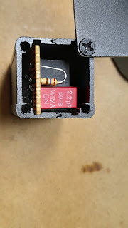
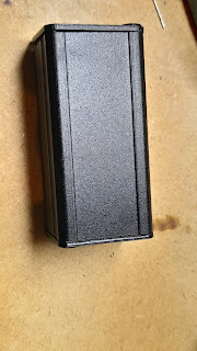
Here is a picture of the isolation transformer with attenuator. The input is from the dbx and the output goes to the ACC1 port, Pins 4 and 2. The transformer I used is an old line isolator for Telephone modems, an ETAL-P1200. I have a few more isolators from old Telecom exchanges but, they are a bit bigger and didn't fit into the case I've had laying around. Also, I took the easy way out in cabling the isolator (not enough space in the case), the doco for the P1200 does show us how to use it properly.


And a blurry photo of my quick build


To connect to the ICOM, I wired a DIN 8 pin to connect to the ACC1 port as followed:
  • Pin 4 (Audio input) and Pin 2 (GND),
  • Pin 3 (PTT) and Pin 2 (GND) using a handfootswitch.

Here is an extract from the ICOM manual.


And here is the new audio profile for the IC-7610 with the AKG HEIL GM5 mic.

Transceiver Setup:
    1. TX SSB Setup
      • TBW (NAR) 200-2500 (TX-BW 2K3) prefered
      • TBW (MID) 100-2700 (TX-BW 2K6)
      • TBW (WIDE) 100-2900 (TX-BW 2K8)
      • TX Treble +5 -2
      • TX Bass -3 0
    2. MOD INPUT
      • ACC MOD LEVEL 20% 15%
      • DATA OFF MOD MIC, ACC <-- MIC needed for VOICE TX
    3. COMP
      • Level 3 6
      • TBW Depends on the mood. (see TX SSB Setup)
Below are a few pics of a second unit I've build. Which, according to the ETAL documentation has better audio transfer characteristics.


The new interface is now connected to the ICOM IC-7610 and the old interface to the ICOM IC-9700. By splitting the output of the dbx, I'm able to use a single Mike for either radio. However, each Radio has its own PTT though.